|
  

Parking Brake
Running Total Hours:
0.0
 | 2007.07.22: (0.0)
The kit as designed by Van's does not include a parking brake.
In my flying experience, I haven't found much use for a parking brake,
except for one situation: getting out of or into the plane when parked
on a ramp that isn't quite level. I always use wheel chocks when
parking, but you have to be outside the airplane to insert or remove
the wheel chocks. The parking brake is used to keep the airplane
from rolling downhill while you're getting in or out.
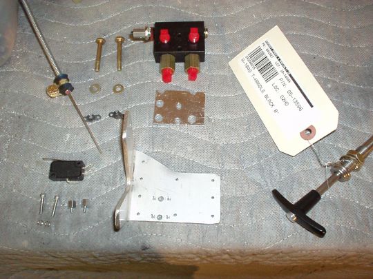
I decided to implement a parking brake using the PV-1 Parking Brake
Valve from Matco,
which has been used successfully by many RV builders. This valve
is available for about $120 from Matco directly, or from Aircraft
Spruce and others. The PV-1 is basically a lever-actuated
two-channel hydraulic check valve, and is installed in-line between
the master cylinders and slave cylinders. When the PV-1's lever
is in the open position (normal flight position), the valve is
"transparent" in both directions, and the pilot has normal brake pedal
operation. When the lever is in the closed position (parking
brake position), the PV-1 becomes a check valve. The pilot
applies pressure using the master cylinders (brake pedals), and the
PV-1 then holds the pressure to the slave cylinders after the brake
pedals have been released.
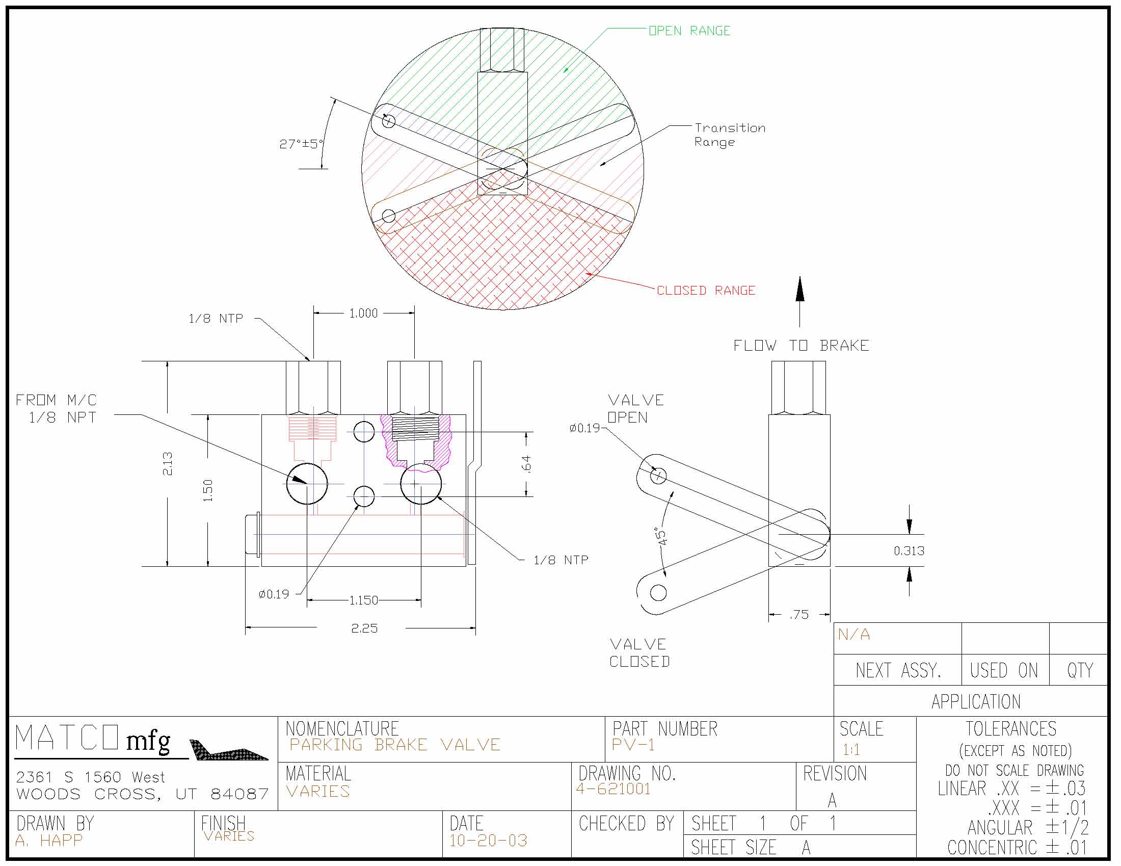
Matco
PV-1 Illustrated Parts List
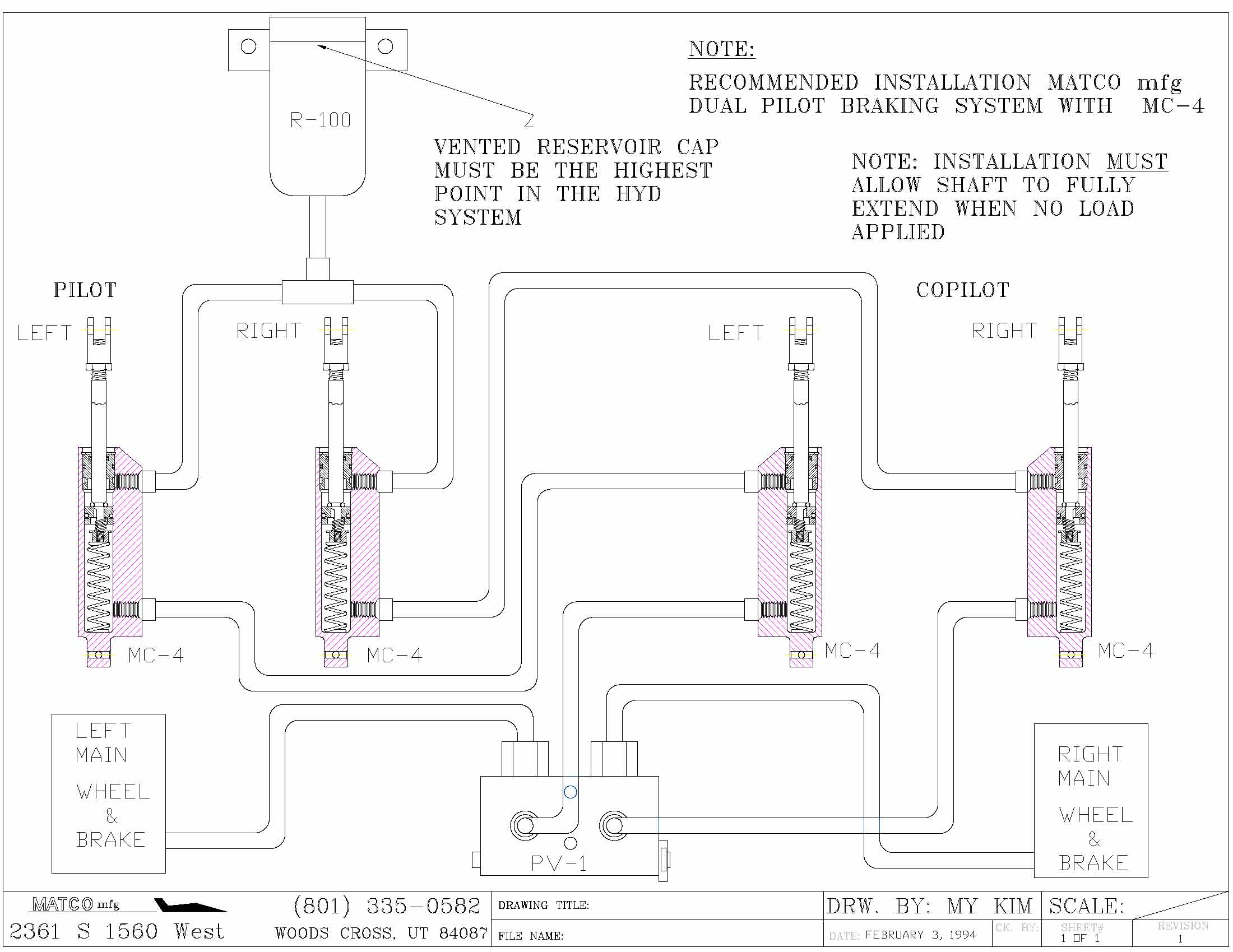
Matco
PV-1 Installation Drawing
Matco Typical
Hydraulic Schematic
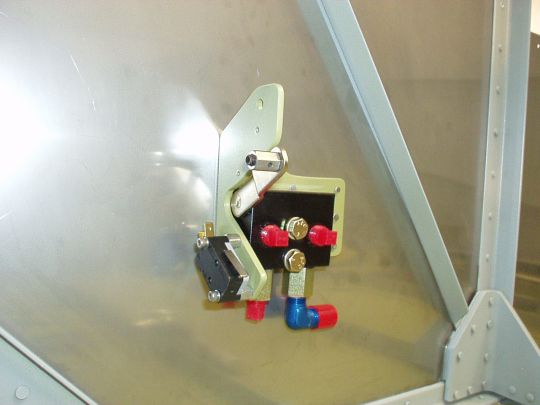
I elected to mount the parking brake valve on the firewall at the
position where the F-6122-1 bracket would normally be installed.
That way, the rest of the plumbing is basically unaffected. Same
hoses, same tubing runs. One limitation with mounting the valve
assembly in this position however is that it protrudes about
2-1/4" aft from the firewall, while F-6122-1 only protruded about
1". So the rudder pedals will have to be positioned such as
to ensure adquate clearance at their maximum forward deflection.
I don't expect this to be a problem, since I'm only 5'9" and
therefore will not be mounting the rudder pedals at the forward most
position anyway.
To control the valve, I'm using a push-pull cable with a T-handle that
will be mounted on the instrument panel or elsewhere within easy
reach. I first bought a cable that locks/unlocks with a 90
degree twist of the handle. Aircraft Spruce p/n 05-15000, don't
know who manufactures it. Pretty inexpensive at $15, but it was
a case of you get what you pay for. Piece of junk. I then
bought a different cable that unlocks with a spring-loaded push button
instead of a twist. Manufactured by ACS
Products (formerly part of Aircraft Spruce) as p/n A-1840, sold by
Aircraft Spruce as p/n 05-13596 for about $45. This is a high
quality cable and is the one I will use. It has an 0.062"
diameter stainless steel wire core and a 0.220" outer diameter
metal casing with an inner teflon lining for smooth operation.
It is sold in various lengths (I bought 8') but can always be
shortened as needed. Max travel is 3.5", locking force 10
lb.
To fasten the control cable outer casing to the mounting bracket, I
bought a control cable clamp, Aircraft Spruce p/n 10464. Being
on the same page of the catalog as the control cable, I assumed it
would fit. Wrong! It had a much bigger diameter than the
cable, so I returned it. Back to basics, I used a 3/16"
cushion wedge type cable clamp (MS21919WDG3), which worked great.
To attach the inner core (the moving wire) of the control cable to the
actuator lever on the parking brake valve I used a "cable end B
nut" (why this is called a "B nut", I don't
know), Aircraft Spruce p/n 05-16245. This worked out
well. Finally got something right on the first try!
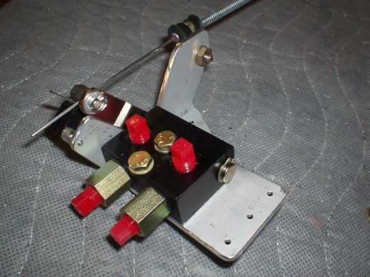
According to the Matco
PV-1 Installation Drawing, the actuator arm needs to be deflected
at least 32º above the horizontal (in the orientation I'm mounting
it) to ensure it's fully open, and at least 32º below the horizontal
to ensure it's fully closed. For maximum robustness, I decided
to incorporate hard stops in both directions as part of my mounting
bracket. I didn't want to rely on the control cable's travel
limit because the cable has a fair amount of flex over its length, and
may also have a significant amount of thermal
expansion/contraction. I set the hard stops at ±35º, which
yields a stop-to-stop cable travel of approx 1.8". Note
that in order to make sure that the valve's actuator lever limits out
on the "valve open" stop of the mounting bracket and not on
the cable's full forward stop, I will have to connect the cable such
that it can't quite reach the cable's full forward stop. I.e.
when limited at the "valve open" stop, the T-handle will
still be sticking out a little bit (say about 1/8") from its full forward position.
In addition to having positive travel stops, I decided to incorporate
a snap-action switch (a.k.a. "microswitch") to sense whether
or not the lever is at the full open (i.e. normal, not parking) position. There will be a
warning light in the cockpit that turns on any time the lever is not
at the full open position (just like the parking brake warning light
in the dashboard of my Toyota). I think this is a worth-while
safety feature, since mistakenly taxiing (or worse, taking off or
landing) with the parking brake on could really ruin your day (loss of
directional control, or having the brake pads catch fire).
[Update 2007.08.30: I just read on AvWeb that an Airbus A319 with 53
passengers aboard landed at Leeds Bradford Airport (UK) with the
parking brake on. Nobody got hurt, but quite a show! Maybe
I should sell my parking brake warning light design to Airbus ;-)]
Snap-action switches are available in many shapes and sizes, and many
electrical and mechanical ratings. This particular application
is very low voltage and current DC (sensing only, I will have a
separate driver circuit for the warning light), and low number of
expected switching cycles (maybe one or two cycles per flight, so say
10,000 over the service life of the airplane), so almost any switch
will do. Still, for ease of future maintenance, I decided to go
with a common form factor that is widely available from numerous
manufacturers and distributers. I will also probably use these
same switches in other parts of the airplane to sense canopy closure,
flap travel limits, etc. Some example p/n's in this form factor:
C&K
(formerly ITT-Cannon?) TM Series: TM-CG-D6-S-T15-40-C (Newark
p/n 07F030)
E-Switch LS Series: LS-085-15-02-F075-C1-A (Digi-Key p/n EG4525-ND)
Omron V Series: V-15G2-1C25-K (Digi-Key p/n SW875-ND)
Cherry D4 Series: D41CR1LD (Mouser p/n 540-D41C-R1LD)
The specific switch I selected was the C&K TM series, because they
are rated for a wide operating temperature range of -55ºC to 150ºC
(-67ºF to 302ºF), which is always a good thing in aerospace, but
especially in this instance where the switch is mounted almost
directly to the firewall. Most other switches are typically
rated for a standard temperature range of -25ºC to 85ºC (-13ºF to
185ºF), which is probably also adequate, but it's nice to have extra
margin. Some of the other switch manufacturers also offer
varieties of their switches that are rated for extended temperature
ranges, but the C&K TM series was the only one I was actually able
to buy in small quantities (available from Newark at $2.78 each, no
minimum quantity).
The switch will be attached to the travel stop flange of my mounting
bracket, spaced with two 1/4" high standoffs so that it hits the
cable end "B nut" but clears the cable itself. The
standoffs are male-to-female, 4-40 thread, with the male end screwing
into my mounting bracket, which is drilled and tapped. The
switch is then attached to the standoffs with 5/8" long 4-40 cap
screws and split washers.
Note that the male threaded end of these standoffs is typically about
3/16" long, while the mounting bracket is only 1/8"
thick. The extra 1/16" protruding inwards causes an
interference with the valve body on one of the two standoffs, so that
standoff's male end has to be "circumcized" down to
1/8" length, easily done with just a little finesse on the bench
grinder.
While I was at it, I also drilled and tapped a pair of mounting holes
for a second switch to sense the full closed position. This
could be used to have another distinct warning for "valve not
fully open, but not fully closed either", i.e. "parking
brake valve in transit". I think this is overkill for this
application, and I probably won't do it. But it was easy enough
to make provisions to mount the switch while I'm still working on the
mounting bracket on the bench. Conversely, it would be very
difficult to retrofit once the mounting bracket is riveted to the
firewall.
The mounting bracket itself is of my own design, pretty simple,
fabricated out of a single piece of 1/8" thick 6061-T6 aluminum
angle. It will be riveted to the firewall using all the rivet
locations intended for the F-6122-1 bracket, plus one additional
rivet. The leg that gets riveted to the firewall is approx
3-1/4" wide, and the leg that forms the control cable mount and
travel stops is approx 1-7/8". I made it from 2-1/2" x
4" x 1/8" angle stock, which is available from Spruce, but
expensive ($15 per linear foot), and I haven't been able to find a
second source. [For future reference: 2-1/2" x 2-1/2"
x 1/8" angle stock, which is far more common, could be used
instead. Then, one of the existing columns of rivets in the
firewall intended for F-6122-1 would just not be used.]
Since the flush rivet heads are on the forward side of the firewall, I
added an 0.063" aluminum shim with clearance holes for the shop
heads on the cockpit side of the mounting bracket, so the valve body
will lay flat on the shim and not on the shop heads. When
riveting the mounting bracket to the firewall, I'll just have to make
sure that none of the shop heads are taller than the shim
thickness. This is fine, since the nominal shop head height is
half the rivet diameter, so for 3/32" diameter rivets that's
3/64", or approx 0.047". The shim also prevents an
interference between the sharp corner of the PV-1 valve and the
rounded inside corner of the mounting bracket.
The valve and shim are finally fastened to the mounting bracket and
firewall with two AN3H-13A bolts. I decided to use plate nuts on
the forward side of the firewall so that the valve can be installed or
removed entirely from the cockpit side of the firewall. This
again is an ease-of-maintenance consideration. The stackup is as
follows, aft to forward (bolt head to plate nut):
AN960-10 washer (0.063" thick)
PV-1 valve (0.750" thick)
shim (0.063" thick)
mounting bracket (0.125" thick)
firewall (0.020")
That's a total stackup thickness of 1.021". The bolt grip
length is 1.000". Note that I'm calling out an AN3H-13A,
the "H" signifying a drilled head, so that the bolts can be
safety-wired to each other.
 |
| 2007.08.18: (1.0)
Riveted the bracket to the firewall with Garnet's help (Garnet on the
gun, me on the bar). We were unable to rivet the nut plates
though, because my rubber-cushioned swivel flush rivet set was too
wide, and interfered with the shop heads of the other rivets we just
set from the other side. Should've seen that one coming. I
see two options: 1. Get a 1" non-swiveling flush rivet set and
give it a shot, or 2. admit defeat and use some pop rivets. Stay
tuned. |
| 2007.09.27: (1.0)
Got a 1" non-swiveling flush rivet set, and with Greg Larson's
help riveted on the nut plates. I had to drill out the first two
attempts because the flush heads stuck out. I think this was
made difficult because the firewall has a fair amount of flex.
But eventually we figured out that the trick is just very very light
pressure on the bucking bar, and the rest went well.
 |
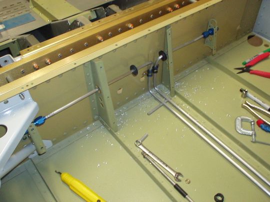
| 2007.10.30: (12.0)
[summay of several evenings] Brought out the output ports of the
parking brake valve at right angles using AN822-4D elbow
fittings. I needed to offset the left and right sides vertically
so they don't interfere with each other, so I made a downwords
extension for the left using an AN911-1D male-to-male and an AN910-1D
female-to-female pipe thread coupling.
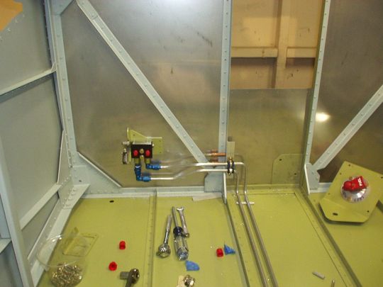
I then completed the brake lines from the parking brake valve to the
bulkhead fittings in my modified F-782B cover support ribs. The
brake lines (centers of the tubes) cross the F-601N-L firewall
stiffener angle at 3" and 3.75" above the floor (F-772), and
1" aft of the firewall (F-601A-2). They are secured with
MS21919-WDG4 cushioned clamps to a little bracket I made that attaches
to the F-601N-L firewall stiffener. The brake lines then jog
down and run aft along the floor at at approx 1.25" and 2.0"
inboard of the F-601N-L firewall stiffener and F-772B-L floor
stiffener. The tube centers are 0.375" above the floor,
i.e. there is 0.25" between the tubes and the floor. They
then ascend at 0.25" from tube center to the center section
bulkhead, i.e. 0.125" between tube and bulkhead, and are secured
to the bulkhead with cushioned clamps. (For future reference, it
works out that the nominal center-to-center run length of the tubes
along the floor is approx 26.375".) They then take a
diagonal jog forward/up, and then a bend outboard to pass through the
F-783B cover support ribs. Keeping the brake lines as far aft as
possible this way keeps them well out of the way of the fuel selector
valve, fuel pump assembly, and fuel lines. Note that instead of
using the center hole in F-783B that Van's intended for the brake
lines, I'm using the upper hole, which Van's intended for electrical
wiring (I'll cut another hole for wiring). This hole lines up
almost perfectly with the center hole in my modified F-782B cover
support ribs (still a very slight jog required to pass through the
hole centers perpendicular to the ribs), and also makes it easier to
avoid interference between the brake lines and fuel lines. I
also enlarged this hole to 0.75", which allows me to pass the
brake line's flared fitting nuts through, and therefore the completed
brake line tubing assemblies can be removed and replaced at
will. I'm also using MS35489-7 (AN931-4-12) rubber grommets
that'll slide into this hole (I put the grommets around the tube
before flaring), although there would be sufficient clearance between
the 1/4" tubing and 3/4" hole that I think it would be fine
without a grommet.
Note that Van's original design requires the builder to bend and flare
the tubing in place, which would be damn-near impossible to do
cleanly, and then the tubing, support ribs, and landing gear mounts
would be impossible to remove without cutting the tubing. I
didn't like that. I wanted to be able to do a neat job of it,
and be able to R&R the tubing, support ribs, and gear mounts
easily and without destroying them, at least during construction, so I
don't end up with chicken and egg problems typical of this part of the
build process. |
|
|
