|
  

Brake Fluid Reservoir
Running Total Hours:
0.0
 | 2009.08.26: (0.0)
This documents what is essentially a complete redesign that I did of
the brake fluid reservoir assembly on the RV-7A.
THE PROBLEMS
The brake fluid reservoir supplied in the kit is a TIG-welded aluminum
cylinder with a pair of mounting flanges and an aft-facing bung, and
is mounted near the top starboard corner on the forward side of the
firewall. The installation is shown on DWG ???. The
general arrangement is ok, but there are many minor problems with the
details:
1. The mounting flanges are welded to the cylinder wall and
essentially form long and relatively weak cantilevers. It is
easy to imagine that with normal flight loads and vibration, these
welds may eventually fail, and indeed some RV owners have reported
this occurring.
2. The top of the firewall angles forward and interferes with the top
of the reservoir, therefore requiring that washers will be added
behind the reservoir mounting flanges to shim it further forward and
away from the firewall. This further increases the potential for
vibrational loads on the flanges.
3. The bung at the bottom of the reservoir is an aft-facing tube that
has female NPT threads to accept a fitting. The problem with
this arrangement is that the tube has to penetrate the firewall,
but no good means for mechanically securing or sealing the penetration
are provided. In essence, one has to drill a clearance hole
through the firewall sufficient for a slip fit for this tube, and then
goop some sort of sealant (proseal, hi-temp RTV, etc.) all around
it. This is not robust as a mechanical bond nor as a gas seal in
the long term, especially given that normal vibration will tend to
cause relative motion between the reservoir bung and the firewall in
this area.
4. The reservoir has only a single bung, whereas it ultimately needs
to feed both the left and right brake systems. Naturally, a
"T" fitting can be used. But this makes the
arrangement prone to working itself loose over time, since normal
motion of the rudder/brake pedals will transmit tortional forces back
to the "T" fitting via the hoses.
POSSIBLE SOLUTIONS
Not satisfied with Van's reservoir installation, I decided to redesign
it to eliminate these deficiencies. I looked at several options:
1. Eliminate the firewall-mounted reservoir altogether and use two
smaller reservoirs mounted directly to the co-pilot's master
cylinders. This arrangement has been used in some production
aircraft, as well as some RV's, and works reasonably well. The
biggest downside I see is the potential for brake fluid spillage in
the cockpit, both during maintenance service (i.e. bleeding the
brakes, checking or topping fluid levels) and during high tubrulence
or other momentary negative-G conditions. [Note that in all the
arrangements discussed, the top of the reservoir is vented through a
filter that should prevent spillage under only very brief negative-G
conditions, such as may be incountered in moderate turbulence.]
2. Design and build my own "ideal" firewall-mounted
reservoir. I ruled this out only because I don't currently have
access to a machine shop.
3. Buy a different (i.e. 3rd party) firewall-mounted reservoir and
design an appropriate installation for it. Ultimately this is
the option I chose.
MY SOLUTION
I looked at several off-the-shelf reservoirs from several
manufacturers, and selected one from Grove
(p/n 067-054) as the best fit for my needs, or at least the best
starting point. It is a machined aluminum cylinder (6061 alloy,
black anodized finish) with a bottom-facing female NPT outlet.
It comes with a mounting bracket that connects to the reservoir itself
using two 10-32 screws, which is nice and sturdy, but that also gives
me the freedom to make a different mounting bracket if necessary (and
it was).
In designing the installation, I wanted to keep the same general
location on the firewall as Van's original design, but eliminate the
problems listed above. In essence, I opted to make the
"T" on the forward side of the firewall, and then have two
separate penetrations through the firewall using AN bulkhead
fittings. Also, I opted for everything (the reservoir and the
fittings) to be secured to a single rigid support bracket that could
then be attached to the firewall as a unit, thereby eliminating any
relative motion due to vibration of the firewall. I played
around with a whole bunch of different ideas and configuations, and
ultimately landed on the following. A picture is worth a
thousand words, so here's several thousand words worth.
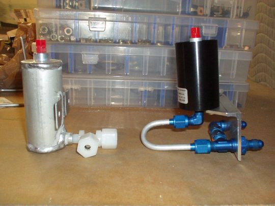
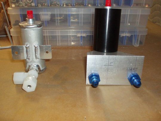
Van's reservoir (left) and mine during initial fitting (right):
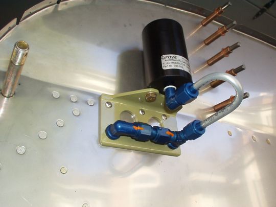
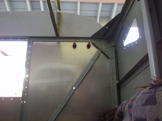
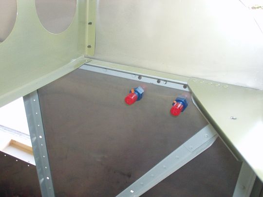
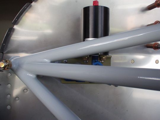
Installed on the firewall:
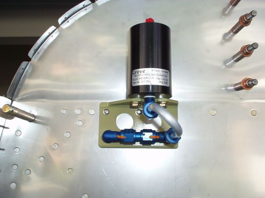
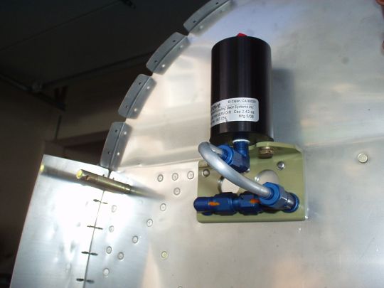
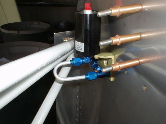
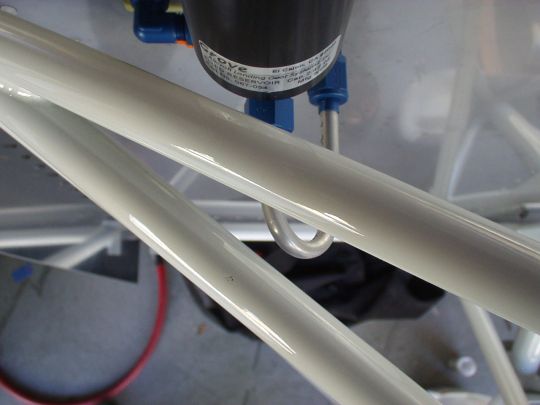
And with the engine mount installed. Hard to judge from the
photos, but the installation (reservoir, tubing, etc.) has better than
1/4" clearance all around from the engine mount as well as the
firewall, ensuring that nothing will ever come in contact even with
engine vibration.
PARTS
The mounting bracket I fabricated from 6061-T6 aluminum, 0.125"
thick 2"x2" angle stock.
The reservoir itself, as mentioned above, is Grove
p/n 067-054.
Instead of the mounting screws and split washers supplied by Grove, I
intend to use AN3H-3A drilled head bolts and AN960-10 washers, and
safety wire.
The fluid fittings are all standard AN hardware (with one
exception**):
One AN822-4D elbow, 90°, 1/8" NPT to 1/4" flared tube.
One AN804-4D bulkhead tee, 1/4" flared tube with bulkhead on the
run.
One AN833-4D bulkhead elbow, 90°, 1/4" flared tube.
One 818-4-4D** straight female-to-female swivel coupling, 1/4"
flared (**AN-compatible but not a standard AN part, purchased from Bonaco).
All the usual AS4824 conical seals, AN819-4D sleeves, AN818-4D and
AN924-4D nuts.
The tubing I fabricated myself (5052-0 aluminum 1/4" aluminum
tubing) and has the following dimensions: 1.19" throat (i.e.
center to center bend diameter) and 0.9" difference in length of
the straight sections. The bend radius is simply that of my
Imperial tubing bender, and the length of the straight sections would
ideally be as short as possible (given the 0.9" difference), but
were dictated by limitations imposed by the design of the tubing
bender and flaring tool that I have. So in a sense, much of the
rest of the installation geometry was designed around that, but all
worked out well.
THANKS
Thanks to the folks at Grove
for putting out a very high quality product, well designed and well
made, as I've come to expect from them. And thanks to Brett
Jarvis at Bonaco
for all his good suggestions and for sending me parts very quickly
when I was ready to do it (we spoke in the late afternoon, UPS was at
my door the next morning). Both Grove
and Bonaco
will certainly be getting more of my business in the future. |
|
|