|
  

Nose Gear
Running Total Hours:
0.0
 | 2008.12.09:
(0.0) Failures of the
nose gear on the RV-xA models has been a highly controversial topic in
the RV community for a few years now. Anecdotally, there seems
to be an alarming rate of occurrences of the nose landing gear leg
buckling, often followed by the aircraft flipping over. Some of
the accidents in question occurred while operating on unpaved or
otherwise rough surfaces, but others occurred on paved surfaces under
what most would consider normal operating conditions. Even under
ideal conditions, the nose gear is known to have a tendency toward
shimmy problems and large magnitude flexing oscillations in the gear
leg. There are
those, including Van's, who insist that there is no problem other than
perhaps poor pilot technique. And then there are those,
including myself and the NTSB, who believe that there are also one or
more design deficiencies that are major contributing factors to these
accidents. Primarily, there are the ground clearance issue and
the wheel rotational resistance issue. The phyiscal properties
of the gear leg itself have also come into questions, but the limited
data that is available on that to date has not revealed a problem.
DESIGN OVERVIEW
The nose gear design on the RV A models is very simple. The gear leg is
made of solid 6150 spring steel rod and is bolted to the engine mount. It
has a circular cross section, and tapers down in diameter toward the
bottom. The main span of the gear leg has a forward sweep angle,
and makes a bend to vertical at the bottom. There, a free-castoring
aluminum fork holds the wheel/axle assembly. A fiberglass
fairing mounts to the fork and covers the wheel assembly.
Another fiberglass fairing covers the gear leg. The fairings
provide aerodynamic drag reduction, but are not otherwise structurally
significant. The gear leg is fairly elastic, and there is no provision for dampening.
ISSUE: GROUND CLEARANCE
It has been suggested that these nose gear failures occurred
because the front of the fork or the bottom of the gear leg made
contact with the runway surface and dug in. This idea is
supported by damage that has been observed on those parts of the
aircraft, as well as grooves on the runway surface at some of the
accident scenes. It makes sense that if that occurs, there may
be enough force exerted on the gear leg to cause it to buckle.
However, that in itself doesn't explain what causes the fork or gear
leg to conact the runway surface in the first place.
The pattern of RV A-model nose gear failure accidents eventually caught the
attention of the NTSB, and a study was commissioned. The
study, NTSB Case No. ANC05LA123 released on June 21, 2007, focused
on the ground clearance issue as the key to this pattern of
accidents. The study found that a number of factors including
the fork design, low tire pressure, heavy firewall-forward
configurations, and uneven runway surface can reduce the ground
clearance to nothing.
REMEDY: NEW GEAR LEG AND FORK DESIGN
Although Van's has always maintained that there was no problem with
the gear design (liability, I understand...), in February 2005, before
the NTSB
study was even commissioned, Van's quietly started shipping a
redesigned gear leg (p/n U-603-3) and fork (p/n WD-630-1). The design change was supposedly
made for manufacturabiliy reasons, but in any case, the new design
provided improved ground clearance. On November 9, 2007,
following the release of the
NTSB study, Van's finally issued Service Bulletin 07-11-09 for the
upgrade of older RV's to the new gear leg and fork. My own
finish kit was shipped in October of 2007, and already included the
redesigned gear leg and fork, so I'm in compliance.
REMEDY: WEIGHT & BALANCE
On November 9, 2007, along with the mandatory Service
Bulletin 07-11-09, Van's
also issued a service letter containing further discussion as well as
operational recommendations related to the nose gear. Most
notably, the service letter recommends a new limitation on weight
& balance. The recommendation is that the maximum static
weight on the nose wheel for an RV-7A should not exceed 375 lb.
I plan to adopt this recommendation as an operating limitation on
my airplane.
The service letter contains graphs for determining weight on nosewheel
as a function of gross weight and CG for a typical RV-7A aircraft.
Alternatively, I could use the actual measured stations of the nose
wheel and main landing gear wheels on my aircraft to calculate it numerically.
REMEDY: TIRE PRESSURE
Van's service letter of Nov 9, 2007 recommends that the nose gear tire
should be kept between 25 and 35 psi. I'll aim for the upper end of
that range, and check it dilligently on a frequent basis.
REMEDY: RUNWAY SURFACE
Although many tricycle gear RV's, including Van's demonstrator aircraft, do
regularly operate on grass or dirt airstrips, I would have to say that
the gear design is not well suited for those types of
surfaces. And the accident history does point to unpaved
surfaces as a major factor. Let's face it: the RV is a
wonderfully verstaile aircraft, but it is not a bush plane. Most
of the flying I do anyway is to destinations with paved runways in
decent condition, so for me that's not a major limitation.
REMEDY: PILOT TECHNIQUE
This should go without saying, in any aircraft. The nosewheel is
for supporting the weight of the nose sitting on the ramp or rolling at taxi speeds. It is not designed to
sustain landing loads; that is what the mains are for. For the RV, with its spindely little gear legs, this is even more
critical than other aircraft. On takeoff, lift the nosewheel off the ground as soon
as practical. On landing, hold the nosewheel off the ground as
long as practical, then let it down gently. Taxiing, or any time
the nosewheel is on the ground, keep the weight off it as much as
practical with up-elevator.
ISSUE: NOSE WHEEL ROTATIONAL RESISTANCE
The stock nose wheel and axle assembly design from Van's (using Matco
components) inherently has a significant amount of friction even under
ideal conditions, and is susceptible to creating extreme amounts of
friction or even to binding completely with only moderate stresses or
slight variations in geometry or axle bolt torque. When the
aircraft is rolling forward, resistance to rotation of the nose wheel
clearly will impose a force on the gear leg trying to bend it
aft. The greater the rotational resistance, the greater the
magnitude of the force will be on the gear leg. Whether this is
structurally significant as a static load is not known, but perhaps
more important is its effect on the dynamics of the entire nose gear
as a system. It has been observed that the amount of rotational
friction in the wheel has a significant effect on the oscillatory
tendencies of the nose gear. Those RV pilots that have replaced
or altered the wheel and axle assembly to eliminate this friction in
various ways report that the nose gear no longer shimmies and
oscillates. Some even report that the difference in overall
rolling resistance in noticeable to the pilot in taxi operations.
Several design attributes seem to be the major contributors to this
rotational resistance. Firstly, the axle assembly design is such
that the wheel bearings are directly squeezed by the axle bolt.
There is no spacer to set the axle geometry and bearing pre-load, so
slight variations in axle bolt torque or flexing under load can have a
significant effect on bearing pre-load. Secondly, the bearings
themselves have rubber seals that rub and create significant
friction. This also increases dramatically with pre-load.
Thirdly, there is nothing keeping the "mushroom" bushings
from rotating themselves, which is what tends to happen once the
bearing drag becomes excessive.
REMEDY: GROVE WHEEL AND AXLE
Grove Aircraft
Landing Gear Systems, Inc. sells a far superior wheel and axle
assembly that corrects the deficiencies in the Van's/Matco stock
design. It uses an axle spacer to precisely set the bearing
pre-load, it includes an anti-rotation pin for the
"mushroom" bushings, and uses bearings with felt seals for
lower inherent drag. The wheels themselves are also of very high
quality, and are available in aluminum or magnesium. I opted for
magnesium to save weight ($30 more, 1 lb. less). Those who have
switched to the Grove product report a tremendous improvement in the
ground handling characteristics of the nose gear, and that the
oscillation problems practically disappear. The part number is
59-2M-RV, which includes Grove's standard 59-2M 500x5 nose wheel and
bearing, plus the axle components specific to the RV-6/7/8/9A (a
different product for the RV-10 is also available).
On a historical note, Van's originally used a nose wheel and axle
assembly made by Cleveland on the RV-6A. Around 1998 they
switched to the Matco product, no doubt because it was cheaper.
It is hard to find solid data, but anecdotally it appears that around
the year 2000 (presumably when the 1998 finish kits started turning
into airplanes) the troubles began. Incidentally, the Grove
design is practically identical to the Cleveland design used on the
early RV-6A. |
| 2008.12.10:
(0.0) Today I went over
to Grove,
which conveniently for me is located 30 minutes away at Gillespie Field, and bought
their 59-2M-RV nose wheel and axle package. Over there I met
Gail, and company founder Robbie Grove, both of whom were very
knowledgeable and friendly and just great all around. These
folks are true aviation enthusiasts, and are excited about innovating
and putting out a high quality product. This is the kind of
company I like to do business with.
|
| 2010.08.09:
(0.0) Another plot
twist... There is an issue with the offset of the valve stem
relative to the centerline of the wheel. In summary, the RV -A
models use a tire size (11x4.00-5) that is smaller than anything used
on certified aircraft (note however that the same tire size is used on
some Lancair, Glasair, and EZ models). While "real"
aircraft tires are available in this size (Aero Classic, Desser, Lamb
/ Cheng-Shin...), the inner tubes available in this size are made and
marketed for go-carts, lawn tractors, etc., not aircraft in
particular. As such, these inner tubes don't conform to the
aviation standard of placing the valve stem along the center
line. More commonly (and nowhere specified that I could find),
the valve stem on these tubes is offset about 3/4" away from the
centerline.
Now, the Matco wheel provided in the kit from Van's indeed has the
valve stem exit hole cut at an offset from the centerline of the
wheel, roughly matching that offset on these inner tubes. The
Grove 59-2M-RV nose wheel however, is actually just their standard
5.00x5 aircraft wheel, and as such it has the valve stem exit hole cut
right on the centerline. This means that with the combination of
this Grove wheel and go-cart inner tube, the tube will be twisted and
the valve stem will be under shear load due to being forced closer to
the centerline of the wheel.
The ideal solution I was hoping to find is a standard aircraft tire
and tube of the same or even similar size, that had the valve stem on
the centerline, and therefore would be compatible with the standard
Grove wheel. But after much research I've come up empty
handed. So it'll have to be the stock tire and tube.
Through my online research I did find though that this issue has
already been noted by others, and remedied by Grove by virtue of
another wheel model (59-4M-RV) with an offset valve stem exit hole
(the valve exit to the outside is also in a slightly different
location that better fits this tube, and does not use a
grommet). I called Grove to ask about it, and they agreed to let me
swap my 2M (which was still unused, in the box) for a 4M. I
drove down there in the afternoon and did the swap.
Note that when I was there, I spoke with Gail, who told me that many
of the 2M wheels have been used with these offset inner tubes for a
long time with no actual problems reported. She said that the 4M
wheel was more just a response to pressure from folks who expressed
the same concern as me, without having actually experienced any tube
failures. I do believe her. But I also do still prefer to
"do it right" than to get away with something that's not
quite right. And since they do have a wheel now that solves the
issue, I'm happier to have it. Again Grove proves to be a
stand-up company who cares about customer satisfaction.
|
| 2010.09.05:
(0.0) Mounted the tire
(see main gear page for general
technique). First attempt was a failure. Pinched the
tube between the two wheel halves. Many others have had this
happen, and I can see why. This is so common that Van's even
ships you two nose wheel tubes by default... Second attempt was
successful. Partially inflated the tube to give it its round
shape (which I also did the first time), but also used my fingers
through center of the bearings to push the tube out from between the
wheel halves as I progressively tightened the wheel tie bolts to bring
the wheel halves together. |
| 2010.11.03:
(0.0) Started putting
together the fork assembly. Firstly, I just took the fork
weldment and cleaned it up (it came very dirty with all kinds of
tenacious residues). I then did a little bit of filing to remove
some surface defects and round over hard corners. Finally,
masked off the brass bushings and threaded holes, prepped the surface,
and shot it with epoxy primer. That should give it a good long
corrosion-free life. I then installed the two cap screws that
act as swivel stops. Used a little Loctite 242 on these
guys. I also installed the MS15001-1 grease fitting
("zerk" fitting) for the swivel joint. Note: Van's
doesn't specify a particular grease to use for the swivel joint, and
different builders seem to be using anything and everything under the
sun without any problems reported. I plan to use Aeroshell 22
simply because that is the grease specified for the nose wheel
bearings, so using the same grease for both there will be less chance
of mishaps. |
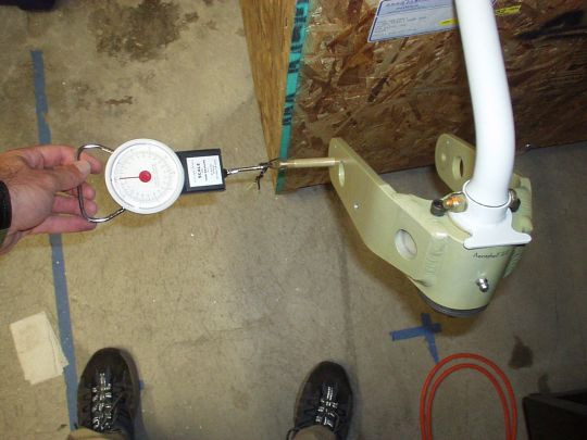
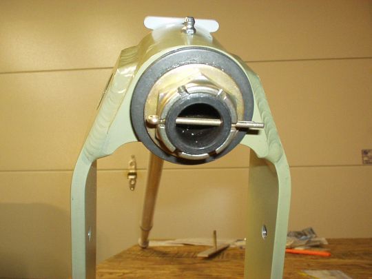
| 2010.11.04:
(0.0) Fitted the
fork to the leg, set the breakout force, and drilled the cotter pin
hole.
 |
|
|