|
  

Engine Mount
Summary
Running Total Hours:
0.0
 |
2009.04.17: (0.0)
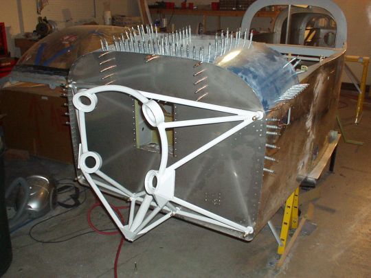
Refer to DWG 46A. My engine mount is Van's p/n WD-739-PC, which
is for Lycoming dynafocal-1, and for the tricycle landing gear
configuration (i.e. includes a socket to mount the nose gear
leg). The engine mount comes from Van's fully welded and
powder-coated.
The engine mount attaches to the fuselage at six points using
3/8" (AN6) bolts. Four of the six points (the four corners)
on the fuselage (firewall, and hard points behind it) have also
already been drilled to 1/4" at the factory, which is
unfortunate, because these holes don't line up very well with the
corresponding holes on the engine mount. I should be able to
enlarge the holes in the fuselage to 3/8" and completely
encompass the existing 1/4" holes, just barely. But this
will not be easy since the existing 1/4" holes are far from where
will be the centers of the final 3/8" holes. This is
another case of Van's (or the QB factory, I don't know which) taking
an extra step without thinking, which only makes my life harder.
Had the holes never been drilled at all, this task would be a
no-brainer. Oh well...
I bolted the engine mount to the fuselage with 1/4" bolts and
some bushings I made of various diameters to try to keep the holes as
close to centered as possible. And then I'm using 3/8" OD
bushings inserted into the engine mount as drill guides to try to
gradually enlarge the holes in the fuselage toward their desired
centers. Work in progress. |
| 2009.04.20: (0.0)
Finished all six holes to 3/8". From 1/4", I enlarged
them with a size "S" drill guided through a brass bushing
(3/8" OD, 0.014" wall thickness) through the engine mount to
keep the drill centered. The drill bit tends to bind when
cutting through the stainless steel firewall, but ultimately the
results were fine. Then I reamed them to 3/8" through the
engine mount, yielding nice clean concentric holes. For the two
bottom center holes, which thankfully were not pre-drilled, I first
drilled them to 1/4" with a bushing (3/8" OD, 1/4" ID)
through the engine mount as a drill guide, and then enlarged them same
as the other four.
Note that the four corners sit nice and flush on the firewall, but the
other two attach points at the bottom center are raised about
0.032" off the firewall. Other builders have reported the
same. Anyhow, so I'll need to shim this gap. The pads
surrounding each hole on the engine mount are 1.25" in diameter,
so the shims should be that diameter or slightly larger. I'll
probably use a AN970-5 washers, which have a 1.375" OD and
0.328" ID (clearance for AN5 bolt), and I'll open up the ID to
0.375" for the AN6 bolts. Note that this also makes the
AN6-24 bolts that are called out in the plans too short, so AN6-25
bolts will be needed.
 |
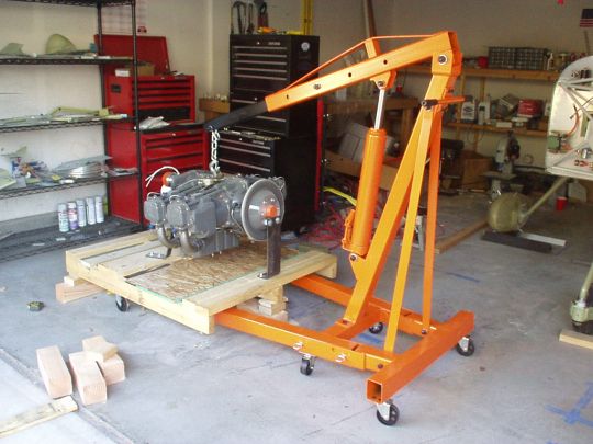
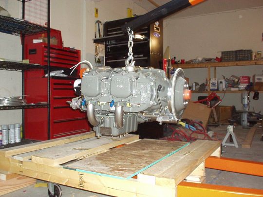
| 2011.07.19: (0.0)
With the firewall prepped and the
fuselage now on the gear, I
proceeded to mount the engine.
Following an article on VAF, my first attempt was to do the top bolts
first. But I then couldn't get the bottom bolts in, so I tried
again the other way. Going bottom bolts first, the top bolts
were also very difficult. But by manipulating the engine with
the hoist, and pulling it into the mount with some ratchet straps, I
was finally able to get it done.
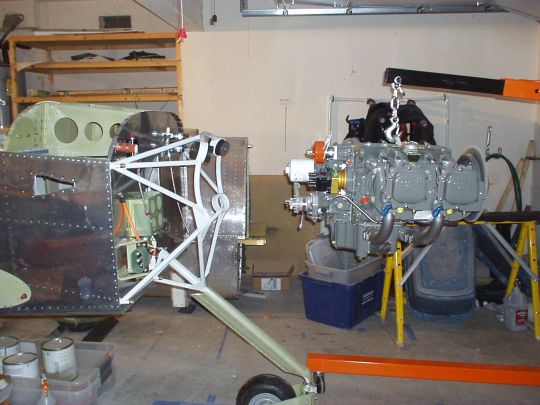
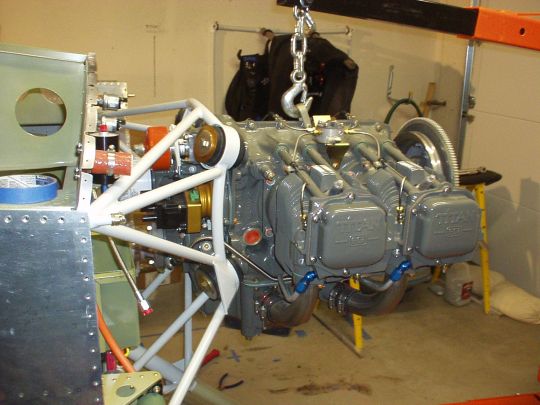
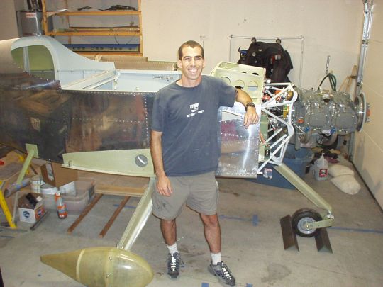
Wow, looks like an airplane! |
|
|