


Antennas
This page summarizes
information about the selection, design, location, and installation of the
various antennas in the aircraft. Relevant resources include AC
43.13-2B chapter 3, as well as installation guidelines from specific
antenna and avionics manufacturers.
VHF Comm
VHF Nav
Marker Beacon
GPS/WAAS
Transponder
ELT
VHF Comm
Aviation-band VHF communication
("comm") signals are
transmitted in the range of 118 to 136 MHz, and are vertically
polarized. Light aircraft typically use rod antennas for VHF comm,
mounted vertically (typically with some slant aft) either on the top or bottom of the fuselage.
Since the comm antenna is used for bidirectional communication (i.e. both
transmit and receive), an aircraft having more than one comm transceiver
will need a separate antenna for each transceiver. It is common to have two comm transceivers in the
aircraft, both for utility (the frequency juggle and/or multi-frequency
monitoring) and for reliability/redundancy (old-style radios failed
often), and most such
aircraft in fact have two comm antennas. For my airplane, I
might only elect to install only a single comm transceiver (a Garmin
GNS-430W), in which case I will only install a single comm antenna. If I
do install a second transceiver, then I'll need to install a second comm antenna as
well.
Note: My current method for handling the radios is to always use comm 1
for my active bidirectional channel (i.e. ATC, or occarionally flight
service or flight watch), and to use comm 2 only as a monitoring frequency
for picking up ATIS,
etc. This method helps keep things somewhat sane, especially in IFR. But
still, monitoring two channels simultaneously, such as trying to pick up
ATIS while also on a busy ATC sector, can get pretty crazy. I'm going to
try as an experiment to avoid this situation by asking ATC to leave the frequency for a
minute to pick up ATIS instead of juggling it using the second
radio. If I find that this method works well, then I will no longer need a
second radio. About reliability/redundancy: modern solid-state comm radios
are far more reliable than their predecessors, so that contingency is less
of a factor. But, I also still carry a hand-held comm in my
flight bag, just in case (along with a headset adapter -- the handheld
comm is useless in flight otherwise). And if all else fails, I guess I'll get my
money's worth on all those lost comm procedures we train on. As a
wise flight instructor once said, airplanes fly because of Bernoulli, not
Marconi (not entirely accurate about Bernoulli, but gets the point
across).
So antenna location, on top of the fuselage, or underneath the
fuselage? Seems like the majority of production airplanes have them
on top, while the majority of RV's have them on the bottom. RV's
with sliding canopies may not have a choice but to put them on the bottom
due to the real estate covered up by the open canopy. But tip-up canopies
don't place any such constraints. So to examine the
trade-offs: Placing the antenna on top will definitely provide better range
while on the ground, which is reportedly an issue sometimes with bottom-mounted antennas. A top-mounted antenna will also be less susceptible to
FOD during ground ops. Placing the antenna on the bottom may provide better range
while in the air, but then again, not necessarily. A bottom-mounted
antenna would be less likely to become a bird's perch on the ramp, and would also be
less noticeable aesthetically. Bottom mounted com antennas are also
often bent aft about half way down the aerial, presumably to provide a
reduced vertical profile for better ground clearance. This also has
the benefit of substantially reducing the antenna's aerodynamic drag.
It does however have a negative impact on the antenna's performance
(higher VSWR which will translate to reduced range). Ultimately, location of the comm antenna
is also largely dictated by minimum
distance requirements imposed by other antennas.
My current plan is to mount the comm antenna on the bottom of the
fuselage, in the center tunnel just aft of the F-705 bulkhead (the rear
spar carry-through), i.e. at the forward end of the baggage compartment
just aft of the flap mechanism. This location offers several
benefits: 1. It provides the antenna with an excellent ground plane of
flat continuous skin for about a 2 ft radius. 2. It places the
antenna along the fuselage's centerline, thereby distributing the
radiation pattern as evenly as possible. 3. It keeps the antenna a
good distance (~ 2 ft) away from projections such as the cabin steps,
landing gear legs, and flaps. 4. This location is close enough to
the main landing gear that it can support a straight comm antenna with
ample ground clearance in a tail low attitude. 5. It keeps the
antenna well away (~ 5 ft) from the transponder antenna, and of course
well away from the GPS and ELT antennas that are mounted on top of the
fuselage.
This location of course places the antenna right under the elevator push
rod. I measured that there is greater than 1.5" of clearance
between the bottom skin and push rod throughout its range of motion.
Using a right-angle BNC connector (Amphenol RF 31-335-RFX) the top of the
connector is less than 1.25" above the bottom skin, so there is
greater than 0.25" clearance. I plan to use this right angle
connector (or a similar one) and run the cable through (perpendicular to)
the rib that forms the right wall of the center tunnel.
Note that I put it aft of the F-705 bulkhead rather than forward of it
because the bottom skin is flat aft of it and not flat forward of it, as
it curves to match the bottom camber of the wing.
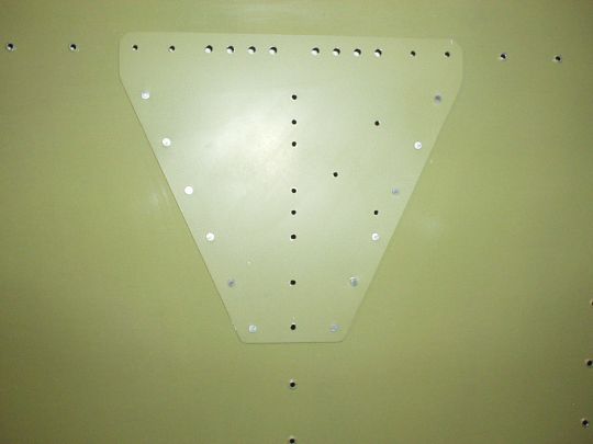
I fabricated a backing plate from 0.062" thick 2024-T3 Al to stiffen
the skin between the bulkhead and ribs, and to spread the load of the
antenna over a greater area than just the antenna base.
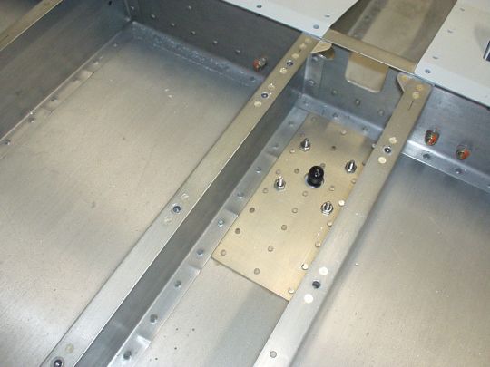
There seems to be a de facto standard for the mounting hole pattern that
is used by a large number of comm antennas from various manufacturers, and
that is what I'm using. I
will most likely use the RAMI
(R.A. Miller Industries, Inc.) AV-17, which is a low profile bent rod
antenna designed especially to be mounted on the bottom of the
fuselage. It weighs 8 oz., generates 0.66 lb of drag at 250 smph,
has a max airspeed of 350 smph and max altitude of 50,000 ft, and max VSWR
of 3.0:1. It costs about $125 from Spruce or Van's. The Comant
CI-122 is very similar and will fit the same mounting hole pattern, but is
about $40 more expensive, so the RAMI is my default choice and the Comant
is a second source backup. (Note that Comant also does not publish
drag data, whereas RAMI does, which I appreciate). Both RAMI and
Comant also have straight (i.e. non-bent) comm antennas that will fit the
same mounting hole pattern (e.g. RAMI AV-10, Comant CI-121), so that's a
fall-back option for me if I find that the bent rod antenna gives me
inadequate performance.
If I later choose to install a second comm, then I have a few decent
options for the second antenna:
Option 1: Place the second antenna also on the fuselage bottom, along the
centerline, further aft. Here there are two competing constraints,
the first being proximity to the other comm antenna, and the second being
ground clearance in a tail-low attitude. I haven't taken exact
measurements, but I suspect that a location somewhere between the F-706
and F-707 bulkheads (i.e. around where the A/P pitch servo is located)
would provide a working compromise.
Option 2: Replace the GPS antenna with a combo GPS
+ VHF comm antenna (really two separate antennas and the necessary filters
all enclosed in a single radome). The Comant CI-2580-200,
CI-2728-200, and CI-2728-410 are approved by Garmin as replacements for
the GA-35 GPS antenna. Conveniently, the CI-2580-200 fits the same
mounting hole pattern as the GA-35 with one additional hole for the comm
BNC connector (and conveniently, the GA-35 also uses the same de facto
standard mounting hole pattern as the AV-17 and other comm antennas
described above).
VHF Nav (VOR/LOC/GS)
VHF omni-range (VOR) signals
are transmitted in the range of 108 to 118 MHz, ILS localizer (LOC)
signals are transmitted in the range of 108 to 112 MHz (a subset of the
VOR band), and ILS glideslope (GS) signals are transmitted in the range of
329 to 335 MHz (the 3rd harmonic of a subset of the LOC band). All
VOR/LOC/GS (which I will collectively refer to as VHF nav) are
horizontally polarized.
Traditionally, light aircraft have used the "cat whiskers"
dipole antenna for VHF nav, or occasionally the "towel bar"
style antenna. In all cases the antenna is mounted in the horizontal
plane, and usually near the top of the vertical stabilizer.
Most antennas are reasonably efficient at the 3rd harmonic, and so an
antenna designed for VOR/LOC can usually also serve the GS. However,
since the actual receivers are different circuits (though they are
typically found within the same avionics "box"), use of the same
antenna for both VOR/LOC and GS requires the use of a splitter, or
preferably a diplexer. In some cases, a nav receiver may have a
single antenna input and perform the diplexing function internally (e.g.
Apollo/Garmin SL-30). In other cases, the nav receiver may have two
separate antenna inputs for VOR/LOC and for GS, and leave it up to the
installer to provide appropriate signals (e.g. Garmin GNS-430W).
Where two separate inputs are provided, one could use a single antenna
with a diplexer, or two entirely separate antennas.
My current plan is to equip the airplane with a Garmin GNS-430W as the
sole VHF nav receiver. Since this unit provides separate VOR/LOC and
GS inputs, I intend to use 2 separate antennas rather than a diplexer to
maximize performance (others have reported a significant difference in
receive range).
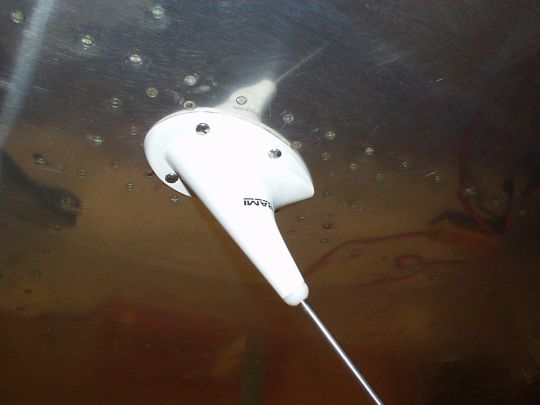
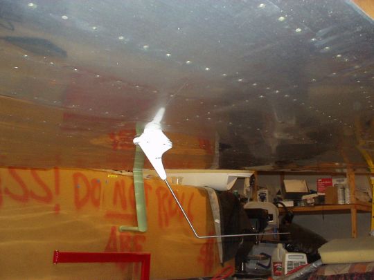
I elected to use the SA-001 antenna, designed by Bob Archer. This
VHF nav antenna is a bit different from those found in most production GA
aircraft, but is actually fairly common in RV's, and reported to have good
performance when installed correctly. It is a gamma-match antenna
designed to be mounted inside a fiberglass wing tip, using the metal wing
as ground. Mounting the antenna inside the wing tip offers some nice
advantages, the most obvious being zero aerodynamic drag. Also,
since the antenna isn't sitting in the breeze, it can be structurally very
modest, which translates to light weight.
I may install one of these in each wing tip, allocating one for VOR/LOC
and the other for GS. Or I may install only a single antenna and use
a diplexer to split the signal for VOR/LOC and GS. Another alternative for the glide slope would be to make/install a
half-wavelength dipole antenna (approximately 16") inside the
cowling. I'll probably hold off on this idea, and only attempt it if
I don't get satisfactory performance from the wing tip antenna.
Note that by having the nav antenna installed in a
wing tip, I will be introducing a lateral offset error of half the wing span to
my indicated course deviation. This should be negligible for VOR
navigation,
and irrelevant to GS, but could actually be preceptible for a LOC approach
on short
final (if I can fly the LOC that precisely ;-). So, given that I'll
likely be based at Gillespie Field, I think I'll use the right wing tip
antenna for VOR/LOC, to keep me away from Rattlesnake Mountain, which is
right (north) of course.
Marker Beacon
Marker beacon (MB) signals are
transmitted on a 75 MHz carrier. They are relatively powerful, and
highly directional straight up. These days we only really use them
as part of an ILS or LOC approach (and they're being phased out even for
that), and so we are usually at 2,000' AGL or lower when we need to pick
them up. This all means that we can get by with a very modest
antenna design and still achieve adequate performance.
Traditionally, light aircraft have used either an L-shaped "sled
runner", or some fancier enclosed antenna, under the
fuselage. An RV can get by with a very simple quarter-wavelength
whip (approx 40") running horizontally inside one of the fiberglass
wing tips. A simple way to do this is to connect the center
conductor of a coax cable to a 40" long strip of aluminum (a la Bob
Archer), or even easier, simply strip the shield off from the last
40" of a coax cable.
Marker beacon is becoming less and less important around here, even for
IFR, and can generally be substituted for with GPS. So I may or may
not even install a marker beacon receiver in my airplane. But I will
probably still install a MB antenna inside one of the wing tips as
described above, just to have. We'll see.
GPS/WAAS
Most panel-mounted aviation GPS receivers
use a "puck"-style antenna. Some of these are actually
active antennas while others are passive, and many GPS receivers actually
require a specific antenna that they've been tested and approved to operate with (the
Garmin 430W comes bundled with the "GA 35" GPS WAAS antenna,
garmin p/n 013-00235-00, AeroAntenna p/n AT575-93GW-TNCF-000-RG-27-NM).
The GPS antenna should be positioned horizontally on the top side of the
aircraft such as to have an
unobstructed view of the entire sky, ideally with minimum shadowing all
the way down to the horizon, in order to have as
many satellites as possible within view at any given time. It should
also be positioned well away from any transmitting antennas to prevent
possible interference, and especially from VHF comm antennas, which are
notorious for radiating harmonics in the GPS band. The Garmin 400W
Series Installation Manual (p/n 190-00356-02 rev. G) section 2.4.1
outlines these requirements and more, in great detail and with relative
priority.
Generally, the best location for a GPS antenna is on top of the
fuselage just behind the canopy. Alternatively, it would be nice to mount the GPS antenna where it won't contribute
to aerodynamic drag if it can be done without significantly compromising
signal reception. One possible option is to locate the GPS antenna under the fiberglass
cowling just forward of the firewall. Some builders have reported
good results with this location (although there is some shadowing by the
firewall), and others have had reliability problems over time,
likely due to excessive heat and/or vibration. Another possible location would be on
top of the glareshield in the cockpit. The view of the sky is a bit
obstructed aft by the roll bar structure, but that is still not very high
over the horizon (maybe 20 to 30°?). Yet another possibility is on a tray on one side
of the F-632A channel that runs under the back window. Here the view
of the sky is partially obstructed on one side by the F-623A channel, in
the front by the roll bar, and in the back by the aft fuselage skin.
But these obstructions are all fairly low on the horizon, so it might
still be adequate.
My plan is to mount my primary GPS antenna (GA 35, for the Garmin 430W)
on top of the fuselage, 3 inches aft of the back window , just 13/16"
left of center, conveniently taking advantage of the F-787 stringer and
F-688 gusset as the recommended doubler so the antenna is not mounted to
unreinforced skin. I expect that
this position for my main GPS antenna should give me the most reliable GPS performance, and I've
given that very high priority as I consider it to be my primary electronic
navigation instrument. The top skin aft of the canopy slopes down at
about 6.5°, which is not quite ideal (Garmin 400W Series Installation
Manual sec 2.4.1 guideline 1 recommends level in normal flight attitude)
but should be close enough I think. This location is likely the best
compromise in terms of shadowing (guidelines 2 and 3c), being several feet
away from the VS, several feet away from and higher than the prop, two
feet aft and only slightly lower than the cabin frame, and having no other
shadowing obstructions above the horizon. In terms of interference
(guidelines 3a and 3b), the transponder and VHF comm antennas will be on
the bottom of the fuselage, so they should be a non-factor. And the
ELT antenna is on top but about 4 feet aft of the GPS antenna (minimum
recommended by Garmin is 2 feet away), and in any case the ELT does not
transmit during normal aircraft operation, so it too should be a
non-factor. The 3 inch distance behind the back window meets
guideline 5, and any other GPS antenna(s) I may install would be in a
different part of the airframe entirely, therefore meeting guideline 6.
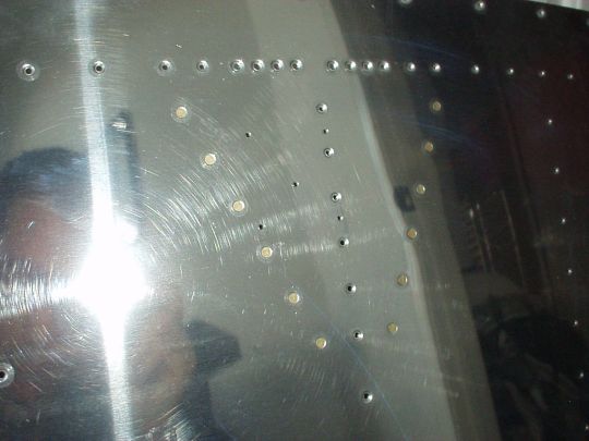
The photos depict five pilot holes that I located and drilled for mounting
the GPS antenna (footprint dimensions sent to me by the good folks at
SteinAir). The four corner holes will be enlarged to 0.17" for
the 8-32 mounting screws, and the center hole will be enlarged to
0.56" for the TNC connector. Note how all five holes are
located within the
F-688 gusset, and two of the mounting holes are also along the F-787 stringer.
If I choose
to install a second GPS receiver in the aircraft (very likely), I will
most likely mount its
antenna on the glare shield.
Transponder
The ATCRBS transponder in the
aircraft receives on 1030 MHz and transmits on 1090 MHz. The signals
are vertically
polarized. Typically, light aircraft use either a 1/4 wave stub "lollipop" or a lower-drag blade-style antenna, mounted vertically
under the fuselage.
Like many RV's, I will likely mount my transponder antenna under the
forward cockpit floor at one of the far outboard-forward corners, near the
fuel tank vents. Note that Garmin specifies that the antenna must be
mounted no less than a 3 ft straight line distance (not cable length!)
from its GTX 327 or 330 transponder. The forward corner falls just a
few inches short of this requirement, but RV builders have reported that
it works just fine.
I will most likely use the RAMI
(R.A. Miller Industries, Inc.) AV-74, which is a blade-style
antenna. It weighs 0.2 lb., generates 0.09 lb of drag at 250 smph,
has a max airspeed of 350 smph and max altitude of 50,000 ft, and max VSWR
of 1.5:1. It costs about $95 from Spruce. (Note: This is a
drop in replacement for the Comant CI-105. The Comant CI-105 is
spec'ed to 400 ktas and 70,000 ft, neither of which is a factor for an RV,
has no published drag data, and costs $135. So RAMI it is.)
Note that this antenna should also support future ADS-B services, whether
using the 1090ES or UAT physical layer. 1090ES ("Extended
Squitter") essentially adds to the message format of the existing
1090 MHz mode-S transmission [it is specified in TSO-C166b]. UAT ("Universal Access
Transceiver") was designed specifically for ADS-B, is more flexible
and will support more services than 1090ES, and operates at 978 MHz [it is
specified in TSO-C154c]. Both 1090ES and UAT are mandated to roll out for operation in the United
States, and it remains to be seen how that'll play out. The RAMI
AV-74 and Comant CI-105 antennas are both spec'ed for 960 to 1220 MHz
operation, so both 1090ES and UAT are covered.
Note that the lollipop-style antennas are typically only speced for 1030
to 1090 MHz, and even at that exhibit a higher VSWR than the broader-band
blade antennas. So with that, and the difference in drag, the blade
antennas are pretty much better all around (except for cost).
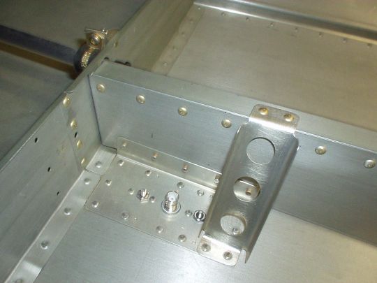
[Update 2010.04.10] I've fabricated and installed a support structure for
a blade-style transponder / ADS-B antenna in the aft fuselage, centered
laterally (or within about 1/4"), and just forward of the F-???
bulkhead. This will mostly be used for ADS-B with a remote-mounted
transceiver, while another antenna (yet to be located) in the forward
fuselage will be used for the transponder.
ELT
The emergency locator
transmitter (ELT) transmits an audio signal on the VHF comm emergency
frequencies 121.5 MHz and 243 MHz, and now also a
digital signal on 406 MHz. GA aircraft under 200 knots typically use
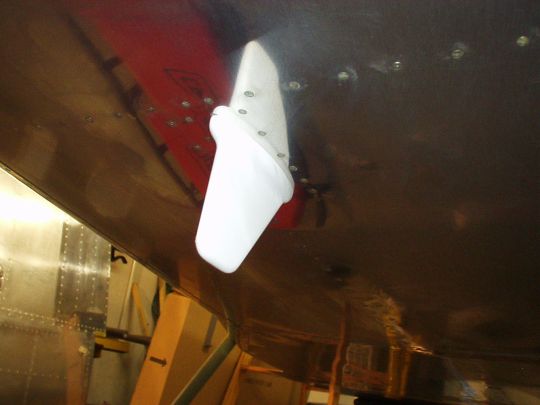
a flexible whip ELT antenna that is either 24 or 15 inches long. My plan is to mount the ELT antenna on top of the fuselage, just aft of the F-708 bulkhead. I did a more detailed write-up on the ELT antenna here.
References